For synchronizing distributed clocks in a local area network (LAN), Network Time Protocol (NTP) and Simple Network Time Protocol (SNTP) are popular methods that are accurate within milliseconds. However, for industrial networks, clock synchronization requires higher accuracy.
IEEE 1588-2008, also known as PTP, offers high accuracy clock synchronization for interconnected systems. There are many sectors that benefit from this protocol, like finance, aerospace, and industry. A representative IEEE 1588-2008 case-of-use is the adoption of this protocol as a synchronization mechanism in the standard for Substation Automation (IEC 61850). Compared to NTP or SNTP, PTP establishes a method for synchronising clocks that can achieve a sub-microsecond precision.
How does PTP work?
A good example of how the PTP protocol works would be like a manual clock. From time to time, the manual clock is out of date, and needs to be adjusted. The difference with an Ethernet network here is that there are nodes and switches in between that propagate their latencies and errors. PTP addresses these problems of synchronising the clocks on an Ethernet network by using messages sent between multiple PTP nodes. PTP calculates the clock offset between master and slave and adjusts it periodically.
An IEEE 1588 infrastructure requires Master Clock equipment to provide clocking reference, Slave Clocks synchronize with the Master Clocks and Boundary Clocks to communicate different clock domains. Additionally, all networking equipment should be time-aware devices in order to maintain the same level of accuracy in the whole network. In the context of IEEE 1588v2 or PTP, the requested featured is named Transparent Clock.
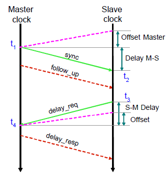
The slave clock requires different measured values in order to get synchronized. Also, the precision of the slave will depend on the precision of the PTP timestamps. The synchronisation process is divided into two phases. First, determine the clock offset and second, determine the measurement of the delay.
The PTP protocol offers different possible timestamping options. It depends on the degree of synchronisation required in the application.
- The hardware assisted approach, timestamps are taken at the Medium Independent Interface (MII), between MAC and PHY chips.
- Pure software solutions take timestamps in the Network Interface Card (NIC) driver or at the application layer.
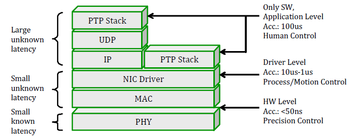
Timestamping at the application layer has the advantage of platform independence. A disadvantage is the relative large variation of the message transit delay through the protocol stack (also called jitter). Timestamping at the driver level is the optimal solution but requires a modi ed network driver:
- Received frames can be stamped at the very beginning of the interrupt service routine (ISR) serving the network interface.
- Transmitted frames are stamped at the very end of the send routine, i.e. at the place, where the frame is passed to the hardware, the MAC controller.
To sum it up, in order to get better synchronization, the timestamp should be as near as possible to the hardware layer.
The following diagram shows a typical application of PTP in Substation Automation System (SAS) application:
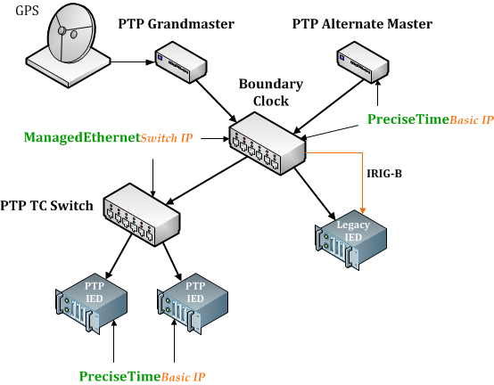
In this scenario, the Merging Units sample current and voltage values and timestamp them using IEEE 1588 synchronized timers. The protection relays, IEDs, process these values and reconstruct the status of the grid using these digital values. The IEDs attending this information can apply any control action.
SoC-e provides technology to integrate these functionalities in a very diverse range of equipment. We offer two types of PTP IP Cores for FPGA. We have one solution which can be a PTP IP Core Master or Slave and another solution only PTP Slave. Our Ethernet Switch IP Cores also support PTP as transparent clock.
We also develop hardware focused on networking and synchronization. We have Evaluation kits that have been designed to evaluate our PTP solutions, as well as end equipment for PTP networks.